

Petroleum Engineers Association | Blog | Things you must know about ESP
What is an electric submersible pump?
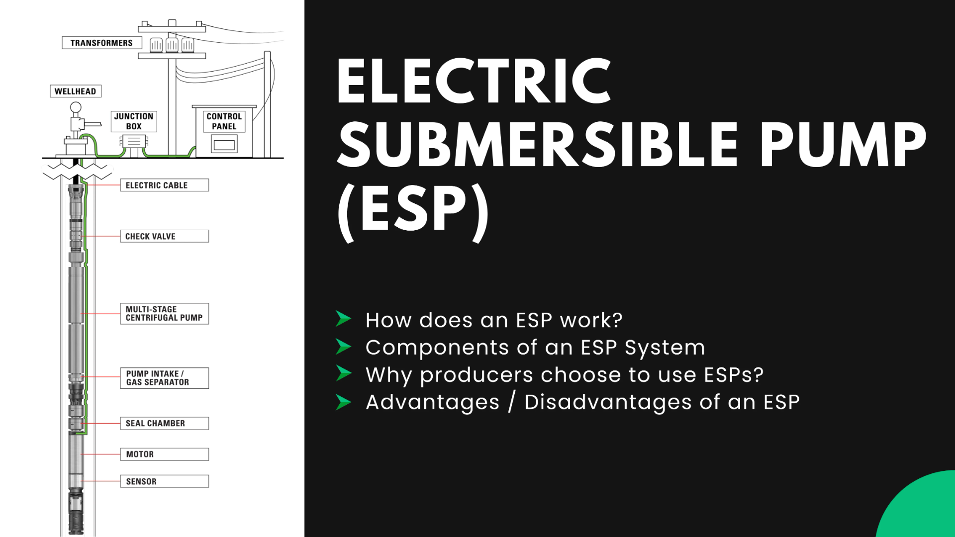
ESP is a form of artificial lift that uses an electric motor to drive a multistage centrifugal pump to lift resources from the well.
Why Producers use electric submersible pumps
Producers use artificial lift systems in more than 90% of oil wells. Producers may choose to use an ESP system because they are quiet, safe and only require a small surface footprint.
An ESP system consists of multiple stages of centrifugal pumps which are connected to a submersible electric motor. The motor is powered by heavy duty cables connected to surface controls.
The motor rotates the shaft which is connected to the pump. The spinning impellers draw in fluid through the pump intake, pressurizing it and lifting it to the surface.
An inverted discharge design is configured the same, with the exception that the pump stages are inverted to pump fluids into the well formation from the surface.
Components of an ESP System
Sensor
To optimize performance, operators can install a downhole sensor that communicates real-time system data such as pump intake and discharge pressures, temperatures, and vibration.
Typically, producers monitor pumps through SCADA, When it detects a pump reading that is outside the set point, a sensor alerts the operator in real time and changes can be made remotely or automatically by the surface controller.
Electric Motor
The submersible pump is powered by an electric motor. The size of the motor and horsepower rating are determined by the number of stages needed to generate sufficient head pressure to lift the liquid to the surface.
The motor temperature will increase as it operates but is cooled by the passing fluid being drawn into the pump. The motor is filled with synthetic oil for electrical protection and lubrication that also helps to evenly disperse the heat that is generated.
PUMP: Shaft, Pump Intake and Stages (Impeller & Diffuser)
Shaft: The shaft connects the motor to the pump impellers through the seal-chamber. The shaft is designed to be as small in diameter as possible without compromising its strength; this allows greater volumes to pass through the pump intake.
Pump Intake —Standard, Reverse-Flow, & Dynamic: The pump intake is where the well fluid enters the submersible pump and is directed into the impellers. Different types of intakes are used depending on fluid properties, particularly the gas-liquid ratio (GLR). Standard designs do not separate gas and are therefore used in wells that produce a very low gas-to-liquid ratio. To separate gas in a well stream with relatively high GLR, producers use either a reverse-flow or rotary pump intake.
In a reverse-flow pump intake the produced fluid with free gas flows up the outside of the reverse-flow intake screen then turns to enter through the perforations at the top of the screen. It then flows down to the intake ports and then back up to the first pump stage. These reversals in direction allow for a natural separation of the lighter gases from the liquid. The separated gas travels up the casing annulus and exits the casing at the wellhead. Longer reversing paths can be utilized to increase the separation of the gas from the liquids.
The rotor or induced vortex forces the heavier fluid to the outside & allows the free gas to migrate to the center of the chamber and exits through the discharge ports back into the well. Gas separator assemblies are often connected in tandem to improve the overall efficiency in high gas applications.
Centrifugal Pump (Impeller and Diffuser)—Stages
The stages of the centrifugal pump are what increase the pressure of the fluid. Each stage is made up of a rotating impeller and stationary diffuser. The stages can be stacked to incrementally increase the pressure until the desired flow rate is achieved.
The fluid travels through a rotating impeller which increases its kinetic energy, or velocity. It then enters the diffuser, converting the energy to potential energy which raises the discharge pressure. The fluid repeats the process in each stage of the pump.
This operation will continue until the fluid reaches the design discharge pressure. The increase in pressure is called the total developed head (TDH) of the pump.
The impellers are crucial to the operation of an ESP because they determine the flow rate. Radial flow impellers have vane angles close to 90 degrees and are usually for lower flow rates. Mixed flow impellers have vane angles close to 45 degrees and are for higher flow rates.
Power cable
The power cable delivers the required power to the ESP motor from the surface. It will be banded or strapped to the production tubing in intervals from below the wellhead to the motor to support its weight and keep mechanical wear from occurring.
Check Valve
A check valve may be threaded into the tubing, a few joints above the pump. It is installed to keep the tubing above the pump full of liquid when the pump is not operating.
Related Blogs:

- Technical Topics
- 7th October, 2025
Oil and Gas Wellsite Safety
12 Steps for Oil and Gas Wellsite Safety1. Watch for Cattle and Other AnimalsWhen you...
- Technical Topics
- 6th October, 2025
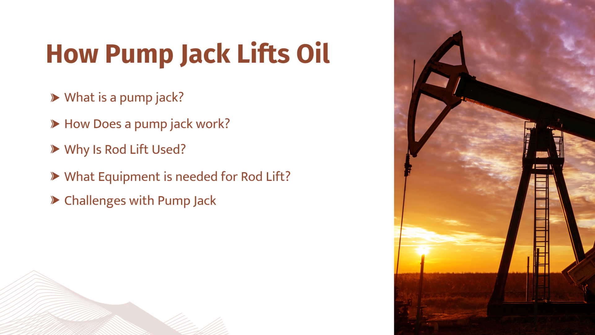
How Pump Jack Lifts Oil
What is a pump jack?A pump jack is a widely recognized piece of equipment used to pum...

- Technical Topics
- 23rd March, 2026
Understanding Hazards and Risks
In Oil and Gas it is important to distinguish between hazards and risks. A hazard r...

Leave a comment on this Blog/Article.